
Igloo Setup
Introduction
Igloo Setup is used to generate configuration files for an Igloo installation, also known as a projection scene.
A projection scene specifies the geometry and properties of a set of screens in a given space.
The application starts up with the initial view shown below.
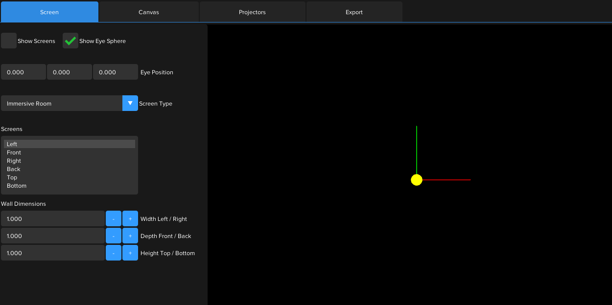
Initial view of Igloo Setup.
The user interface consists of four tabs - Screen, Canvas, Projectors and Export, which are intended to be used sequentially. These represent the stages in the Igloo Setup modelling pipeline. The workflow begins by defining the geometry of the Screen. The Canvas tab uses the screen dimensions to determine the pixel resolution of the space. Likewise, the Projectors tab uses the canvas to specify the projector regions and other attributes. Finally, the configuration files are generated in the Export tab.
Screen
The Screen tab specifies the geometry of the projection scene.
The geometry is specified as a Screen Type with the following types supported: Immersive Room, Cylinder and Dome.
Note that the screen dimensions should reflect the area covered by the projection screen only.
The Screen starts with a text box entry specifying the Eye position. It is followed by a dropdown menu used to specify the Screen Type. The Show Screens checkbox shows the dimensions of individual screens.
Note that the test pattern displayed to represent the screen type consists of 6 faces of a cube mapped on to the geometry of the screen. Each face is labelled with front, back, left, right, top or bottom and contains an igloo logo together with a grid pattern and solid circles in each corner.
Immersive Room
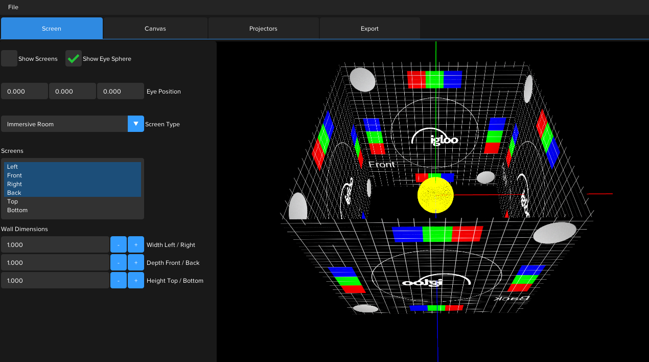
Create a box with specified Width (distance between Left screen and Right screen), Depth (distance between Front screen and Back screen), and Height (distance between Top screen and Bottom screen).
The Screens listbox enables the corresponding views (Left-Front-Right-Back-Top-Bottom) in the scene. The coordinates of these views are automatically updated from the dimensions of the box.
Cylinder
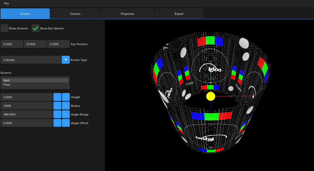
Create a cylinder scene with a given Radius (radius of the circle at the base of the cylinder), Height (distance from the base to the top of the cylinder), Angle Range (number of degrees in the circle e.g. 360 for complete closed cylinder) and Angle Offset (number of degrees to rotate the test pattern about the vertical axis).
The Wall-Floor items in the Screens listbox enable the corresponding wall and disk (floor) views in the scene. The coordinates of each screen are automatically updated from the cylinder parameters.
Dome
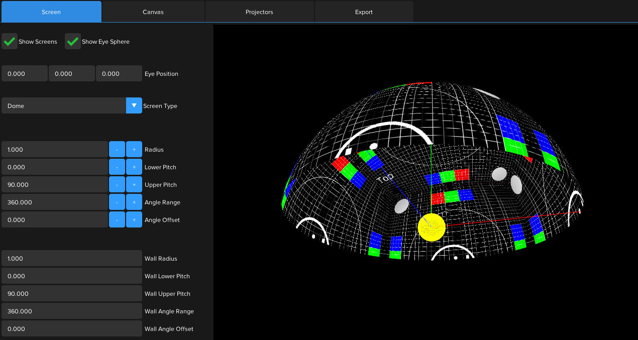
Create a dome scene with a given Radius (radius of the circle at the base of the dome), Angle Range (number of degrees in the circle e.g. 360 for complete closed dome) and Angle Offset (number of degrees to rotate the test pattern about the vertical axis).
The dome is modelled as a hemisphere and can be adjusted using the Lower Pitch and Upper Pitch parameters. Typically, an Igloo dome will use a front-facing projector setup with the projectors located at the top of the dome. In this case, the Upper Pitch value of 90 should be reduced so that the non-projected area where the projectors are located is defined. The Lower Pitch value of 0, represents the equator of the sphere. Adjusting this parameter allows for domes which have a bottom edge above or below the line of the sphere’s equator.
The coordinates of each screen are automatically updated from the dome parameters.
Canvas
The Canvas tab displays a planar layout of the screens generated in the projection scene. The screenshots below illustrate examples of canvas layout for an immersive room and a cylinder projection scene respectively.
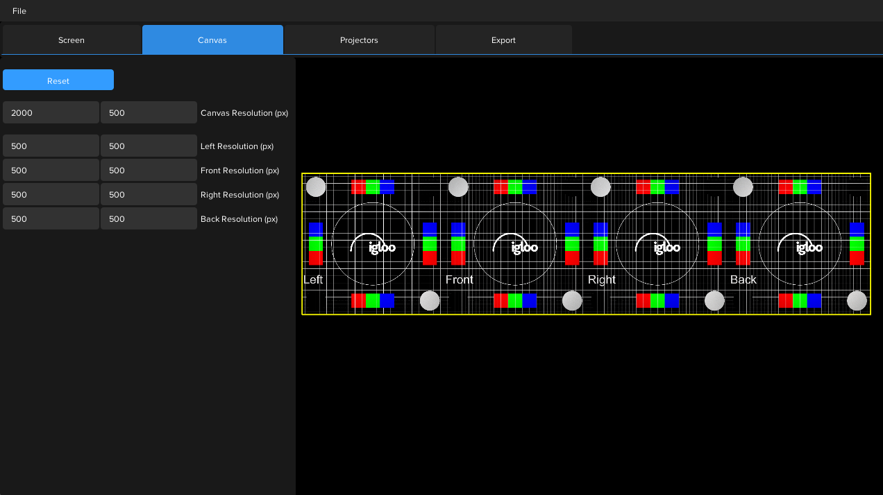
Canvas layout for an immersive room projection scene.
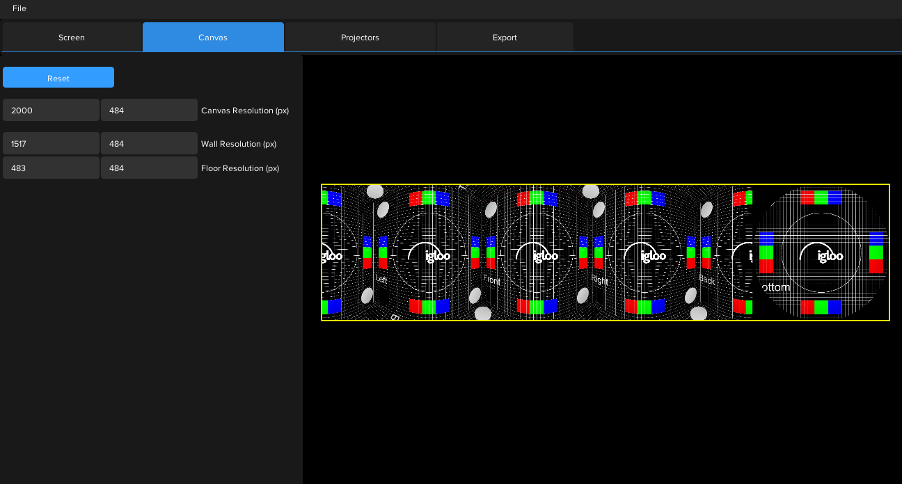
Canvas layout for a cylinder projection scene.
The canvas region is a composition of all screens in the projection scene with empty space in between. The canvas border is an axis aligned bounding box whose purpose is to give a visual cue of the canvas region and is drawn as thick yellow line.
Canvas Topology
The topology of the canvas can be adjusted to suit the installation. For a projection scene with no floor projection, the topology would typically be a horizontal row of screens. However, if the horizontal resolution is greater than 16k pixels, then moving some of the screens to form a grid instead of a row will allow the canvas to fit within the 16k x 16k limit.
For a projection scene with floor projection, it is common to have a grid arrangement, with the floor screens, positioned below the screens used for the walls. The advantage of this approach is that the width of the walls corresponds to the width of the canvas, and this has benefits when moving and scaling content. Also content can be moved from the walls to the floor with an intuitive ‘downward’ action. The illustration below shows how the floor screens can be repositioned using the left mouse button to drag them to a new location.
Moving the floor screen below the walls.
Canvas Resolution
The Canvas Resolution (px) values give the overall canvas resolution in pixels specified in width and height respectively. The canvas resolution is calculated using the resolution of one of the width and height parameters together with the aspect ratio of the screen. Enter the known value of one of the parameters, based on the immersive space design drawings. The other dimension will then be automatically calculated and updated.
The height and width values of each of the screens which make up the projection scene are also calculated automatically. These are displayed below the Canvas Resolution as width, height pairs and labelled Left Resolution, Front Resolution, Right Resolution etc.
Projectors
The Projectors tab presents settings which control the appearance of the test image and defines how many projectors are used in the immersive space.
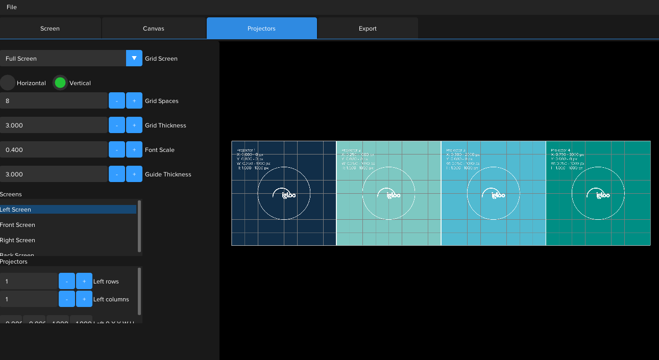
The Projectors tab with test image preview.
Grid Spaces, Grid Thickness and Font scale are parameters affecting the appearance of the test image. A test image preview is displayed to help visualise the effects of changes.
For Cylinder projection scenes with floor projection, Guide Lines, with a Guide Thickness parameter, can also be added to the test image to help with the warping alignment.
Each Screen can also be edited to modify the number of projectors. To add a second projector to the left screen, for instance, we’d change the number of columns to 2:
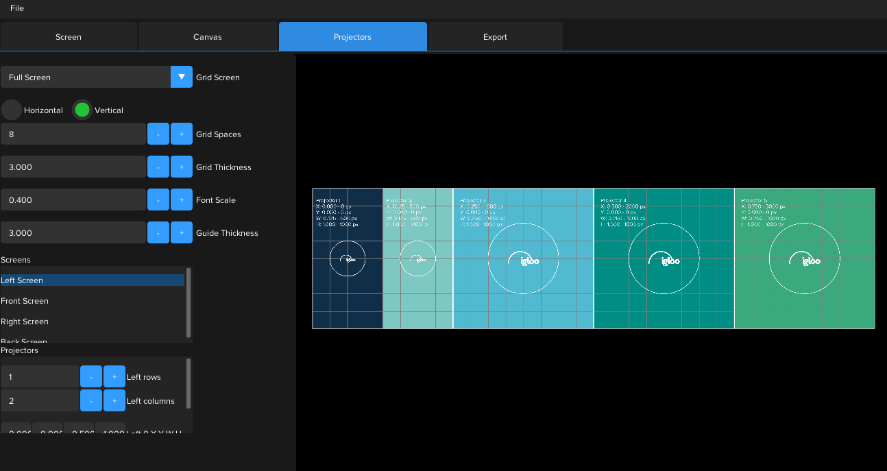
Modifying the number of projectors for a screen.
Export
The Export tab enables the exporting of the generated configuration files.
An export folder can be selected which acts as the destination for the files when the Export button is pressed.
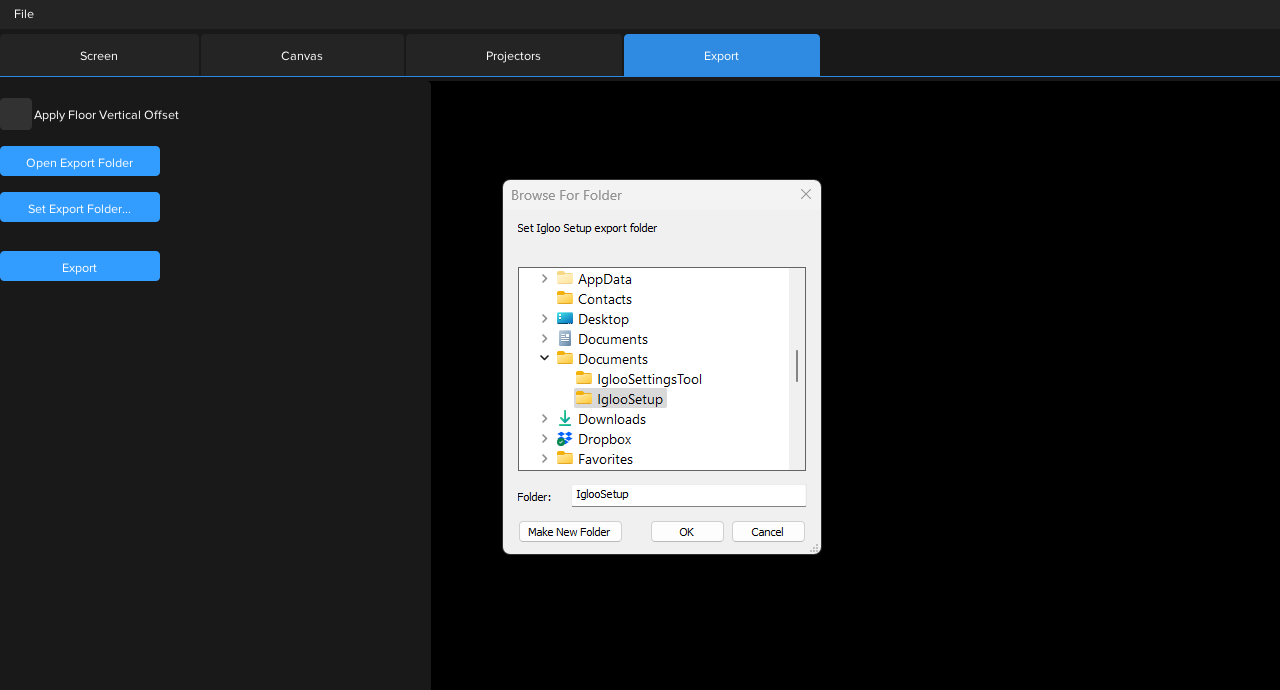
Selecting an Export Folder.
Upon exporting, a collection of files will be generated, each organised within a folder structure that mirrors the corresponding target application. The Igloo Warper files include AppSettings.xml, masks.png, and testImage1.png, while the Igloo Core Engine files encompass screenModel.mtl, screenModel.obj, and a suite of XML files, including CanvasSettings.xml and TruePerspective.xml.
Igloo Warper files
IglooWarper/AppSettings.xml
IglooWarper/masks/masks.png
IglooWarper/test images/ testImage1.png
Igloo Core Engine files
IglooCoreEngine/models/screenModel.mtl
IglooCoreEngine/models/screenModel.obj
IglooCoreEngine/models/testImage.png
IglooCoreEngine/settings/CanvasSettings.xml
IglooCoreEngine/settings/TruePerspective.xml
IglooCoreEngine/settings/unity/displaySettingsOverride/IglooSettings.xml
IglooCoreEngine/settings/unity/IglooSettings-Displays.xml
IglooCoreEngine/settings/warping/canvasMask.png
You can drag the screen model and true perspective files directly onto the ICE console window to replace and load them
AppSettings.xml
To integrate AppSettings.xml into the Igloo Warper settings file located at C:\ProgramData\Igloo Vision\IglooWarper\AppSettings.xml, it is advisable to copy the relevant portions from the export folder to the Warper's file.
TIP - copy the AppSettings.xml file from C:\ProgramData\Igloo Vision\IglooWarper to the Igloo Setup export folder before clicking the Export button. This will modify the file with the relevant settings and it can then be copied back to its original location.
masks.png
The masks.png file only pertains to Cylinder projection scenes with floor projection, where a mask is applied to the Canvas view
ScreenModel.mtl, ScreenModel.obj
The screenModel.mtl and screenModel.obj files should be copied to the ICE models folder, located at C:\ProgramData\Igloo Vision\IglooCoreEngine\models. They are utilized in ICE as a preview tool to visualize the ICE canvas in the projection scene, as evidenced in the Screen tab of the ICE Desktop UI.
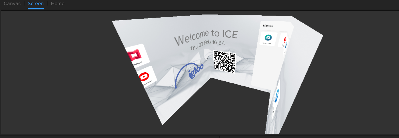
Screen tab in ICE for preview of content.
TestImage1.png
The testImage1.png file can be shared with content creators and used during the initial setup of the projection scene. It is recommended to copy it to the Warper test images folder located at C:\ProgramData\Igloo Vision\IglooWarper\test images, where it can be displayed on the Warper canvas to ensure the warping and blending settings are correct.
TruePerspective.xml
Finally, the TruePerspective.xml file should be copied to the ICE settings folder at C:\ProgramData\Igloo Vision\IglooCoreEngine\settings. This file is instrumental in generating perspectively accurate views for each screen in the projection scene when displaying 360-degree content.
CanvasSettings.xml
The CanvasSettings.xml file should also be copied to the ICE settings folder, where it is used to establish the default canvas resolution when creating new workspaces and when calculating which regions of the canvas to apply rotation to see. Further details regarding the Canvas Configuration can be found in the ICE Documentation. Canvas Configuration - ICE Documentation