
At some point you will want to route the Canvas from Igloo Core Engine out of your computer, ideally to a really big screen. This can be achieved by configuring one or more Screen windows, and optionally Warping and Blending the output within those windows.
The Igloo Setup Tool automatically generates the Screen Window and Warping Setting files for you
Screen Window Settings
Window Settings are configured in the ScreenWindowSettings.xml, typically found at
C:\ProgramData\Igloo Vision\IglooCoreEngine\settings
One or more Windows can be configured, with each Window displaying a subsection of the Canvas.
<windows>
    <window>
        <winXPos>1920</winXPos>
        <winYPos>0</winYPos>
        <winWidth>1920</winWidth>
        <winHeight>1080</winHeight>
        <startX>0.000000000</startX>
        <startY>0.000000000</startY>
        <subWidth>0.000000000</subWidth>
        <subHeight>1.000000000</subHeight>
    </window>
	<window>
        <winXPos>3840</winXPos>
        <winYPos>0</winYPos>
        <winWidth>1920</winWidth>
        <winHeight>1080</winHeight>
        <startX>0.500000000</startX>
        <startY>0.000000000</startY>
        <subWidth>0.500000000</subWidth>
        <subHeight>1.000000000</subHeight>
    </window>
</windows>
-
winXPos
The X position of the top left corner of the Window in screen coordinates
-
winYPos
Y position of the top left corner of the Window in screen coordinates
-
winWidth
The width of the window in pixels
-
winHeight
The height of the window in pixels
-
startX
The starting X position of the canvas subsection to be drawn into the window, in normalised coordinates i.e. 0-1
-
startY
The starting Y position of the canvas subsection to be drawn into the window, in normalised coordinates i.e. 0-1
-
subWidth
The width of the canvas subsection to be drawn into the window, in normalised coordinates i.e. 0-1
-
subHeight
The height of the canvas subsection to be drawn into the window, in normalised coordinates i.e. 0-1
-
stereoFormat
The stereo output setting for individual windows, The possible values for this tag are:
0 : Top-Bottom
1 : Side-by-Side
2 : Left Eye Only
3 : Right Eye Only
Examples
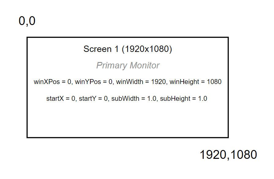
This example assumes you have one 1920x1080 screen and you want to display the entire canvas on this screen.
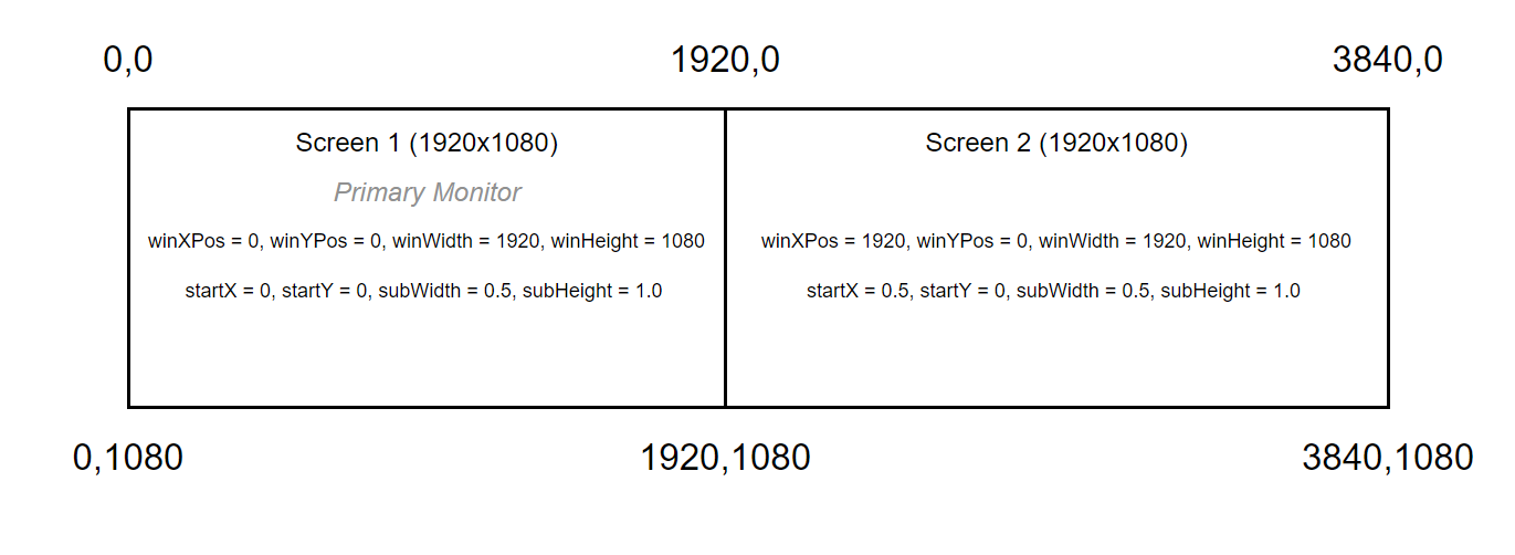
This example assumes you have two screens each 1920x1080, and you want to display the left half of the canvas on Screen 1 and the right half on Screen 2.
Output Warp & Blend
The Warping and Blending can be applied to the Output Windows to alter the geometry and blending between projectors to create a seamless image. Igloo Core Engine Supports a number
Igloo Setup
The Igloo Setup can be used to generate Warp & Blending files which are applied to Igloo Core Engine’s Output windows as well as other configuration settings.
See Igloo Setup for more info on the Igloo Setup tool
Scalable Warp & Blend
Igloo Core Engine supports warp and blend through the integration of the Scalable SDK. Scalable Display Technologies
Scalable settings are configured in the EditorWIndowSettings.xml, found at
C:\ProgramData\Igloo Vision\IglooCoreEngine\settings
<warpType>2</warpType>
<Scalable>
	<outputResX>15360</outputResX>
	<outputResY>2160</outputResY>
	<invertOutputY>0</invertOutputY>
	<Mesh>
		<filePath>C:\ProgramData\Igloo Vision\IglooCoreEngine\warping\Cylinder\ScalableDataOrthographic.ol</filePath>
		<invertInputY>1</invertInputY>
		<inputRect>
			<startX>0</startX>
			<startY>0</startY>
			<width>1</width>
			<height>1</height>
		</inputRect>
		<outputRect>
			<startX>0</startX>
			<startY>0</startY>
			<width>1</width>
			<height>1</height>
		</outputRect>
	</Mesh>
</Scalable>
MPCDI
Igloo Core Engine supports MPCDI (Multiple Projection Common Data Interchange) files for output warping and blending. MPCDI is an ‘almost’ standard format used by many 3rd party calibration tools to define projector layouts, geometry correction meshes, and blend regions.
“The Multiple Projection Common Data Interchange (MPCDI) Standard developed by VESA’s Multi-Projector Automatic Calibration (MPAC) Task Group, creates a standard data format for multi-projector alignment systems, allowing these systems to produce data that can be easily utilized and integrated by a range of devices, programs and displays.“
Applications that output MPCDI files include Vioso, Scalable Displays, Fly Elise
When MPCDI is enabled, Igloo Core Engine reads the MPCDI file and applies the geometry and blending to its output windows.
Settings are configured in the EditorWindowSettings.xml, found at
C:\ProgramData\Igloo Vision\IglooCoreEngine\settings
Example MPCDI xml data for two projectors.
<MPCDI>
  <outputResX>3840</outputResX>
  <outputResY>1200</outputResY>
  <filepath>C:\ProgramData\Igloo Vision\IglooCoreEngine\warping\mpcdi_v1.zip</filepath>
  <Region>
    <outputRect>
      <startX>0</startX>
      <startY>0</startY>
      <width>0.5</width>
      <height>1</height>
    </outputRect>
  </Region>
  <Region>
    <outputRect>
      <startX>0.5</startX>
      <startY>0</startY>
      <width>0.5</width>
      <height>1</height>
    </outputRect>
  </Region>
</MPCDI>
outputResX / outputResY
This typically matches the total resolution of all combined windows.
Regions
An MPCDI file contains one or more regions, each describing how a subsection of the canvas maps to a specific projector.
Igloo Core Engine uses these regions to map the correct part of the warped canvas into each screen window. Each region specifies an outputRect, using normalised coordinates (0–1).
outputRect
Example for a two-projector blend:
Region 1
startX = 0.0
width  = 0.5
Region 2
startX = 0.5
width  = 0.5
This means:
-
The left projector receives the left 50% of the warped canvas.
-
The right projector receives the right 50% of the warped canvas.